
"張" Character Milling
My first project using a CNC mill. This character is my family's last name.

Project Report
Justin Chang Stauffer
Operation 1: Cavity Mill Roughing
Operation 2: Planar Wall and Floor Finishing
Operation 3: Contour Area Finishing
Operation 4: Cavity Mill Finishing
Operation 5: Cavity Mill Finishing (part 2)
In Conclusion:
flatten out the curve. Thus, after changing the height of the tool, I was not able to zero it properly since the middle had already been removed. I zeroed from the corner of the piece, which led to some inconsistencies in the finish of the piece; there are slightly deeper circles cut into each corner in which the 0.125” tool was utilized.
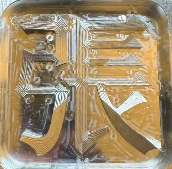
Lastly, the part was very sharp, and the edges were rough due to the horizontal bandsaw. I wanted to smooth these out so as to prevent anyone else from cutting themselves. I filed the edges and deburred the piece, and used tape to remove as much aluminum dust as possible. In the future, I would likely attempt to mitigate this by dulling the edges with a process directly during manufacturing.
As I am new to the physical milling machine, I learned a lot from this project. Among them, the biggest lessons included the sizing of tools, regarding both the standard sizes but also the height upon insertion into the collet, as well as generally seeing how the feeds and speeds affected the actual machine. Going through the process in full once definitely changed how I interpreted the modeling and manufacturing in NX, and helped me understand a lot more regarding every step of the process.
In the future, revisions may include the gap sizing and the dulling of the edges as mentioned before. I also may lean towards less complicated patterns as much as possible. Also, even if the piece may not require it, it appears to generally be a good idea to face mill it regardless.
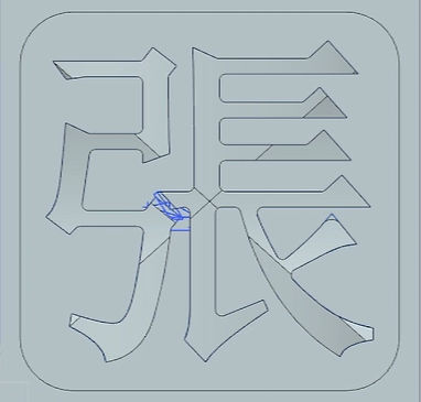
A part was to be created out of aluminum with a 4” x 4” face. The original CAD part is shown; the character is contoured so as to fit the requirements. There were four required manufacturing operations. However, due to the small geometries in sections of the part, five operations were used in the manufacturing of the part, displayed in order below.

A roughing operation was used with a large (0.5”) end mill to quickly remove excess material. It is generally optimal to use a larger end mill for the initial roughing operation, and the half inch tool was chosen based on the geometry size.
An initial finishing operation was used with a medium (0.25”) end mill to define the general shape of the character. The quarter inch tool was chosen based on the geometry sizes. As the inside wall is approximately .25 inches away from the outer points of the character, this operation would efficiently remove the majority of the material surrounding the character. As before, the larger tool size leads to a faster operation– but once again, additional smaller tools will be necessary to complete the process.

The contour surfacing was done next using a large (0.5”) ball mill. For this operation, a larger tool is always better– however, this size was chosen for convenience, as I was unsure what sizes of ball mills would be available. This step was chosen before further cavity mill finishing processes, as the area mill would act similarly to the initial roughing cavity mill by removing relatively large swaths of material. If this step was performed last, further cavity mill finishing operations would by default remove as much material as possible from these areas, a redundant process which would only add time, as the area mill would pass through these areas regardless.
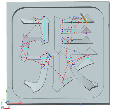
Two final cavity mill finishing operations were performed. The smallest gaps in the geometry were approximately 0.11 inches, leading to an awkward sizing. Thus, a finishing operation was initially done with a 0.125 inch end mill to remove most of the remaining excess material. While the smaller end mill could have done both operations 4 and 5, this was deemed optimal as it would take much less time. This was finished up in step 5 with a smaller end mill.

The second cavity mill finishing operation was done using a 0.0625 inch end mill. As mentioned earlier, operation 4 removed most remaining material. Operation 5 only finished remaining small gaps which were too narrow for the 0.125 inch tool to reach.

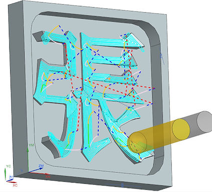
Machining was done with one setup. The block was mounted face up, and remained in position until the process was fully completed, as shown.
As this was my first time using the mill, there were multiple minor issues throughout the process. Firstly, the size of the part geometry did not take tool size into account, as I originally did not know that tools only came in specific sizes. It would have been better to make all parts at least 0.125 inches apart, and thus remove operation 5.
The biggest problem resulted from the height of the tools; although I checked the 0.0625” tool to ensure it would fit, I forgot to scale the 0.125” tool to the right height to reach the bottom of the geometry. I realized this between operations 3 and 4. The operation had to be stopped, and I had to re-fit the tool. This led to some issues with the z axis zeroing. As my part was only for decorative purposes, I did not mill the upper face to